A network is a configuration of machines that exchange information among themselves. For the network to function properly, the information originating at a sender must be transmitted along a communication line and delivered to the intended recipient in an intelligible form. Because different types of networking software and hardware need to interact to perform this function, network designers developed the concept of the communications protocol family (or suite).
A network protocol is a set of formal rules explaining how software and hardware should interact within a network in order to transmit information. The Internet protocol family is one such group of network protocols. The group is centered on the Internet Protocol (IP). Both version 4 (IPv4) and version 6 (IPv6) of IP are supported.
The other members of the Internet protocol family include the Transmission Control Protocol (TCP), the User Datagram Protocol (UDP), the Address Resolution Protocol (ARP), the Reverse Address Resolution Protocol (RARP), the Internet Control Message Protocol (ICMP), the Internet Group Management Protocol (IGMP), and the Neighbor Discovery Protocol (NDP). Note that not all of these protocols are supported by both IPv4 and IPv6, although TCP and UDP are common to both.
The entire Internet protocol family is popularly referred to as TCP/IP, reflecting the names of the two main protocols. TCP/IP provides service to many different types of host machines connected to heterogeneous networks. These networks may be local area networks (LANs), such as one you might install in a single building, but they may also be wide area networks (WANs), such as those based on the Point-to-Point Protocol (PPP).
TCP/IP was originally developed by the United States Department of Defense (DoD) to run on the ARPANET, a packet-switching wide area network first demonstrated in 1972. The ARPANET later became part of a wide area network known as the DoD Internet, or, for short, the Internet. Today, the Internet (based on IPv4) consists of many networks including the National Research and Education Network. The Internet is truly international extending into many countries. It also has gateways to several independent networks which may offer a limited range of Internet services.
Limitations in the number of available IPv4 addresses and in the scalability of routing led to the development of IPv6 as the replacement for IPv4. Sometime in the future, the Internet will migrate to IPv6, but in the meantime, the IPv4-based Internet will continue to be the one that most people use.
Many popular texts use the term Internet to describe both the protocol family and the wide area network. This text uses the term TCP/IP to refer to the Internet protocol suite and the term Internet when referring to the network itself.
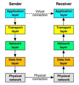
The TCP/IP protocols enable communication between pairs of hosts, or ``peers'', on a network. The TCP/IP protocol structure can be conceptualized as a series of layers, or ``stack'', between an application and the network. Each protocol layer on one peer has a corresponding layer on the other peer. To the application, it appears that it has a virtual connection to an application running on another host. In reality, data is passed over the network in the physical form that the network can handle. Each layer is required, by design, to handle communications in a predetermined fashion. Each protocol formats communicated data and appends information to or removes information from the data. Then the protocol passes the data to a lower layer on the sending host or a higher layer on the receiving host, as illustrated in ``Sender/receiver interaction''.

Sender/receiver interaction
The interface between the application and the transport layers is termed a transport interface. Interfaces such as sockets and TLI/XTI eliminate the need for applications to know about the transport layer in detail. For more information about the programming interfaces to the transport layer, see Using network programming interfaces.
``Encapsulation/decapsulation of application data within a network stack'' shows how each layer adds (or removes) header information to data traveling away from (or toward) the application layer. The process of adding header information is termed ``encapsulation''; removing header information is termed ``decapsulation'' or ``unencapsulation''.
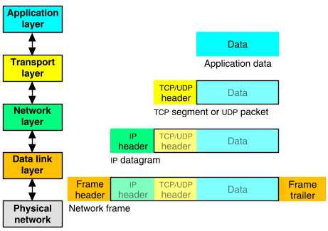
Encapsulation/decapsulation of application data within a network stack
Networking application programs send messages or streams of data to one of the Internet transport Layer protocols, either the User Datagram Protocol (UDP) or the Transmission Control Protocol (TCP). These protocols receive the data from the application, divide it into smaller pieces called TCPsegments or UDP packets, add a destination address, and then pass the packets down to the next protocol layer, the network layer.
The network layer encloses the packet in an Internet Protocol (IP) datagram, adds the datagram header, decides where to send the datagram (either directly to the destination system or indirectly via a router or gateway), and passes the datagram down to the data link layer.
The data link layer accepts IP datagrams, encapsulates them within frames that are specific to the network hardware such as Ethernet, Token-Ring or Fiber Distributed Data Interface (FDDI), and transmits these over the network.
Frames received by a host are processed through the protocol layers in the reverse order. Each layer strips off the corresponding header information, until the data ends up at the application layer. Frames are received by the data link layer which strips off the frame header and trailer, and sends the datagram up to the network layer. The network layer strips off the IP header and sends the packet up to the transport layer. The transport layer strips off the TCP or UDP header and sends the data up to the application.
As hosts on a network can send and receive information simultaneously, data may be traveling both up and down the layers of the networking stack at the same time.
``Networking stack support for the TCP/IP protocols'' illustrates the relationships between the various protocols that are supported within the stack.
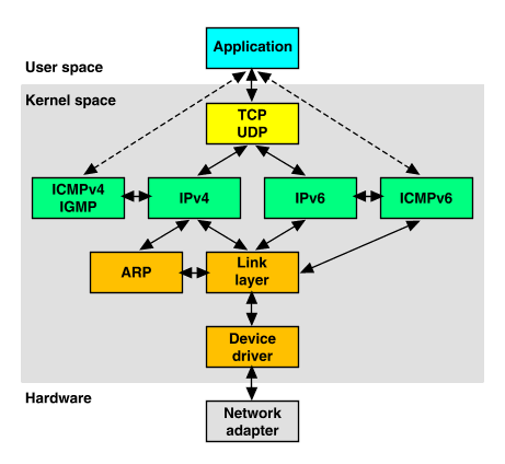
Networking stack support for the TCP/IP protocols
This arrangement is termed a ``dual-stack'' as both IPv4 and IPv6 are supported; the path that data takes is determined by the IP header on incoming datagrams or by the IP address format used by applications in outgoing datagrams.
The following sections provide an overview of how each protocol layer handles messages:
A variety of TCP/IP protocols exist at the application layer including:
See also ``Other application layer protocols'' for a description of various other applications.The Telnet protocol enables terminals and terminal-oriented processes to communicate on a network running TCP/IP. It is implemented as the program telnet(1tcp) on the local machine and the daemon telnetd(1Mtcp) on the remote machine. telnet provides a user interface through which two hosts can open communications with each other, then send information on a character-by-character or line-by-line basis.
telnet includes a set of internal commands that allow fine control over its operation.
The telnetd daemon on the remote host handles requests from the telnet command.
The File Transfer Protocol (FTP) transfers files to and from a remote network. The protocol includes the ftp(1tcp) command on the local machine and the ftpd(1Mtcp) daemon on the remote machine. ftp lets you specify on the command line the host with whom you want to initiate file transfer and options for transferring the file. The ftpd daemon on the remote host handles the requests from your ftp command.
ftp includes a set of internal commands that allow fine control over its operation.
The procedure for setting up an anonymous FTP server may be found in ``Configuring File Transfer Protocol (FTP) servers''.
The Domain Name System (DNS) provides domain-name-to-address-mapping of hosts and mail recipients on a network. For information on how to implement DNS on your network, see ``Configuring Domain Name System (DNS) servers'' and the named(1Mtcp) manual page.
Other application layer protocols exist that are also implemented as a program on the local machine and a daemon on the remote machine. Examples of these are rlogin(1tcp) and rlogind(1Mtcp), which permit a user to log on to a remote machine; rsh(1tcp) and rshd(1Mtcp), which enable the user to spawn a shell on a remote machine; and finger(1tcp) and fingerd(1Mtcp), which permit a user to obtain information about users on remote machines.
To avoid having an excess of daemons running at all times, the daemon inetd(1Mtcp) is initiated at startup time. After consulting the /etc/inetd.conf file (see inetd.conf(4tcp)), inetd runs the appropriate daemons as needed. For example, the daemon rlogind will be run by inetd whenever there is a request for a remote login from another machine. Note that rlogind runs only when the remote login request is made and only for the duration of the remote login.
The TCP/IP transport layer protocols are the Transmission Control Protocol (TCP) and the User Datagram Protocol (UDP). These protocols allow application programs to communicate over the IPv4 and IPv6 network protocols. Both TCP and UDP use source and destination port numbers to tell a host how it should process the message.
Higher-level protocols and applications use UDP to make transient datagram connections, and TCP to make long-lived stream connections. The sockets and TLI/XTI programming interfaces provide access to these protocols.
Whether TCP or UDP is used depends on the network application invoked by the user. For example, telnet uses TCP to make a connection to a remote system, and name-to-address resolution via DNS is usually performed using UDP.
TCP provides reliable delivery of streamed data over a connection established between protocol ports on networked hosts. TCP ensures that data is not damaged, lost, duplicated, or delivered out of order to a receiving process. This prevents programmers from having to build such safeguards into applications.
TCP can transfer a continuous byte stream simultaneously in each direction between two hosts. It divides each stream into segments for transmission and reassembles the stream from received segments.
TCP can recover data that is damaged, lost, duplicated, or delivered out of order. It achieves this reliability by assigning a sequence number to each segment that it transmits, and requiring a positive acknowledgment (ACK) that the remote host has received it. If an ACK is not received within a timeout period, TCP retransmits the segment. The receiver uses the sequence numbers to order segments that may be received out of order, and to eliminate duplicates. The integrity of the data is verified by recalculating the segment's checksum. If this disagrees with the value in the received header, the receiver discards the segment and waits for the sender to retransmit.
TCP governs the amount of data sent to it by returning a window size with every ACK. The window indicates the amount of data that may next be sent. This allows TCP to prevent incoming data overflowing its buffer.
TCP allows many processes within a single host to use the TCP communications facilities simultaneously. A port number and host IP address uniquely identify a socket. A pair of sockets uniquely identifies a connection.
TCP initializes and maintains information for each data stream including sequence numbers, window sizes, and connection state.
The format of a TCP header is illustrated in ``TCP header format''.
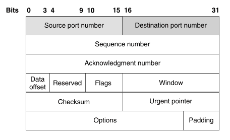
TCP header format
A TCP header contains the following fields:
UDP provides connectionless datagram communication between applications on networked hosts. As the sender does not know which processes are active on the destination host at any given moment, UDP uses a destination protocol port number (a positive integer) to specify the type of service that is required from the remote host. A protocol port receives and holds messages in queues until an application is ready to retrieve them.
UDP provides connectionless, unreliable message delivery in a similar manner to IP. It offers no assurance that datagrams will be delivered nor does it protect against duplication. Applications that require reliable delivery of datagrams must implement their own reliability checks when using UDP. The receiving application can use the source and destination port numbers and checksum in the UDP header to verify that a message has been delivered correctly. Applications that require reliable delivery of streams of data should use TCP.
The format of a UDP header is illustrated in ``UDP header format''.

UDP header format
A UDP header contains the following fields:
The Internet network layer protocols (IP, ICMP, and IGMP) handle machine-to-machine communication including IP routing. The protocols accept requests to send packets (along with the network address of the destination machine) from the transport layer, convert the packets to datagram format, and send them down to the data link layer for further processing.
This section contains information about the following network layer protocols:
The Internet Protocol (IP) provides unreliable, connectionless packet delivery. IP is connectionless because it treats each packet of information independently. It is unreliable because it does not guarantee delivery. That is, it does not require acknowledgments from the sending host, the receiving host, or intermediate hosts.
An IP datagram consists of a header to which is appended a segment or packet from a higher layer transport protocol. The format of an IPv4 header is illustrated in ``IPv4 header format''.
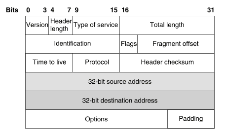
IPv4 header format
An IPv4 header contains the following fields:
A TCP/IP network routes a packet according to the destination IP address, an address provided by the IP protocol on the sending host. IPv4 addresses are 32-bit numbers that uniquely identify every host computer connected to the Internet. This 32-bit address is typically represented as four decimal numbers separated by dots, for example:
202.16.208.51The network address (the part of the address that identifies your network) and the host address (the part that identifies an individual host on your network) must all fit into this 32-bit number. The number of hosts you can configure for your network decreases as the length of the portion occupied by the network address increases.
The network address is the leading portion of the IPv4 address for every host in the network you manage. The network address identifies part of a total IPv4 address as the network, and leaves the rest of the IPv4 address to identify a particular host on that network.
The Network Information Centers or NICs (including the original InterNIC) assign network addresses for the IPv4-based Internet. As different organizations usually manage different numbers of hosts, an NIC traditionally assigned a network ID belonging to one of the three classes, A, B or C, based on how many hosts were expected to be connected to the network. Each class uses progressively more of the IPv4 address to identify the network, and therefore leaves you with fewer numbers to uniquely identify your hosts. See ``IP address'' for a table of the address classes and reserved address ranges.
Unless your organization has many host systems and needs a large address space, you will usually obtain your network address indirectly from an Internet Service Provider (ISP) or from an Internet Registry (IR) rather than directly from an NIC. The extent of the network address space that you are assigned is now specified by a CIDR-style prefix followed by a trailing slash (/) and number of bits. For example, the network address ``202.16.208/24'' would allow space for up to 254 hosts on what would traditionally have been termed a class C network. See ``Subnetting and Classless Interdomain Routing'' for more information.
The host address is the trailing portion of an IPv4 address that uniquely identifies a host within your network. A host address cannot be all binary 0's or 1's. The numbers available to use as host addresses depend on the class of your network (see ``Network address'') or the length of its CIDR prefix (see ``Subnetting and Classless Interdomain Routing''), and whether you are further subnetting the network (see ``Subnet address'').
If you have more than one physical network within your organization but only one network address, you can turn part of the host portion of your address space into several subnet addresses. This is usually called ``subnetworking'' or ``subnetting''.
See ``Setting up subnets'' for more information about subnetting. You can also use the Subnet Calculator to work out how to partition your network into subnets.
Internet Protocol version 6 (IPv6) represents the latest evolution of the Internet Protocol from version 4 (IPv4). While IPv4 has allowed the development of a global Internet, its future is limited by two factors:
IPv6 extends the maximum number of Internet addresses by using 128-bit addressing. Such a large address space should be able to handle the ever-increasing number of Internet addresses well into the future. As both IPv4 and IPv6 protocols may coexist on the same network, an orderly migration from IPv4 to IPv6 may be made without seriously disrupting an operational network.
Finally, IPv6 has been designed to provide the additional benefits over IPv4 of simplified packet header processing and improved option support.
IPv6 addresses consist of eight 16-bit words, that together form a single 128-bit address. For comparison, IPv4 addresses consist of four 8-bit words resulting in a 32-bit address. The increased size of the IPv6 address greatly increases the number of available IP addresses.
The standard notation for IPv6 addresses is to represent the address as eight 16-bit hexadecimal words, each separated by a ``:'' (colon), for example:
2EDC:BA98:0332:0000:CF8A:000C:2154:7313This notation is capable of some simplification. It is not necessary to specify the leading zeros of a word, provided that there is at least one numeric value in each field of the address. The above address could also be written as:
2EDC:BA98:332:0:CF8A:C:2154:7313.As a large number of IPv6 addresses contain multiple words with value 0, the notation ``::'' can be used to represent a single contiguous group of zero-value words within the address. Some examples are shown below:
   3762:0:0:0:0:B03:1:AF18            3762::B03:1:AF18
   2EDC:BA98:332:0:CF8A:C:2154:7313   2EDC:BA98:332::CF8A:C:2154:7313
   FF02:0:0:0:0:1:FF54:7313           FF02::1:FF54:7313
   FF0E:0:0:0:0:0:0:101               FF0E::101
   0:0:0:0:0:0:0:1                    ::1
   0:0:0:0:0:0:0:0                    ::
IPv4 addresses that are encapsulated within IPv6 addresses can be represented using the original IPv4 dot (.) notation, for example:
0:0:0:0:0:0:172.32.67.15
0:0:0:0:0:FFFF:172.32.67.15
Using compressed notation, these addresses would be represented as:
::172.32.67.15
::FFFF:172.32.67.15
In previous releases of UnixWare, the IPv6 implementation was implemented within the networking libraries over an IPv4 network stack. This meant that any IPv6 address had to be able to be mapped directly onto an IPv4 address. This is achieved using an ``IPv4-mapped IPv6 address'' with the following format:
0000:0000:0000:0000:0000:FFFF:x1.a2x.x3.x4which may be written in compressed form as:
::FFFF:x1.x2.x3.x4where x1.x2.x3.x4 is a valid IPv4 address. The
0000:0000:0000:0000:0000:FFFF: part was prefixed or removed by a
library routine to simulate the use of IPv6 addresses.
No IPv6 addresses actually passed through the network layer.
In UnixWare 7 Release 7.2, the networking stack supports both IPv4 and IPv6, and frames containing both types of datagram may be transmitted across the same physical network. IPv4-mapped IPv6 addresses allow IPv6 applications on Release 7.2 systems to service requests from both IPv4 and IPv6 hosts coexisting on the same network.
All applications that use an IPv6 listening socket bound to the IPv6 wildcard address (::) will be able to respond to requests from both IPv4 and IPv6 systems on the same network. If the source address was from a system with an IPv4 address, this will be automatically converted to an IPv4-mapped IPv6 address when a connection is accepted. The stack, not the library, handles all necessary conversion between IPv4-mapped IPv6 and IPv4 addresses for transmission on the network. ``Operation of an IPv6 server on a dual-stack host'' illustrates how the kernel handles incoming requests to a server process that is listening on an IPv6 listening socket.
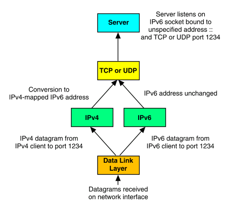
Operation of an IPv6 server on a dual-stack host
When an application on a dual-stack host opens a TCP socket or sends a UDP datagram, the form of the destination address determines whether an IPv4 or an IPv6 datagram is sent over the network, as illustrated in ``Operation of a dual-stack host for outgoing datagrams''.
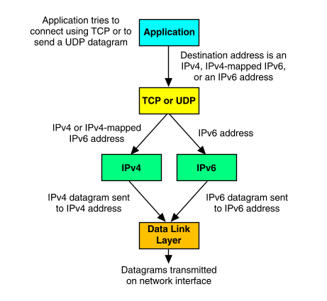
Operation of a dual-stack host for outgoing datagrams
IPv4-compatible IPv6 addresses are IPv4 addresses represented in IPv6 format, padded with nulls in the high-order words:
0000:0000:0000:0000:0000:0000:x1.x2.x3.x4which may be written in compressed form as:
::x1.x2.x3.x4where x1.x2.x3.x4 is a valid IPv4 address. This form of address may be used by IPv6 systems that need to communicate, but which are separated by routers or gateways which cannot route IPv6 datagrams. The stack on the transmitting system encapsulates the IPv6 datagram by prepending an IPv4 header to create a IPv4 datagram. This allows IPv6 datagrams can be ``tunneled'' over existing unmodified IPv4 networks and routers.
IPv6 increases the IP address size from 32 bits to 128 bits. This allows it to support nested levels of addressing hierarchy, a much greater number of addressable hosts, and simple autoconfiguration of addresses.
IPv6 has three types of addresses (defined in RFC 2373):
The format of a unicast address determines the scope in which it can be used:
FE80.
FEC0.
``IPv6 unicast address scopes'' shows the address formats for the three types of scope.
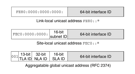
IPv6 unicast address scopes
Two special unicast addresses are:
::::1Other types of IPv6 addresses include IPv4-mapped and IPv4-compatible IPv6 addresses which are used during the transition from an IPv4- to an IPv6-based Internet, and 6bone IPv6 addresses used for testing IPv6 before it is fully deployed.
The scope field in a multicast address limits the forwarding of multicast datagrams:
FF01 (well-known) or FF11 (transient).
FF02 (well-known) or FF12 (transient).
FF05 (well-known) or FF15 (transient).
FF08 (well-known) or FF18 (transient).
FF0E (well-known) or FF1E (transient).
Well-known multicast addresses are:
FF01::1FF02::1FF01::2FF02::2FF05::2FF02::1:FFxx:xxxxFF02:0000:0000:0000:0000:0001:FF catenated with the final
24 bits of the unicast or anycast address.
FF01::101FF02::101FF05::101FF0E::101See RFC 2375 for more information about IPv6 multicast address assignments.
An anycast address is indistinguishable from a unicast address. A unicast address becomes an anycast address when more than one interface is configured with that address.
Mechanisms that allow a node to boot up and start communicating with other nodes over an IPv4 network include static configuration, RARP, BOOTP, and DHCP. These work fairly well, but each has its drawbacks. Static configuration makes it difficult to change addresses, RARP does not supply other useful configuration information, and RARP, BOOTP and DHCP all require that the host broadcast and are dependent on a remote server.
IPv6 introduces the concept of ``link-local scope'' to IP addresses. This allows a host to construct a valid address from the predefined ``link-local prefix'' and its local identifier. The local identifier is typically derived from the medium access control (MAC) address of the interface to be configured. Using this address, the node can multicast rather than broadcast to a server. For a fully-isolated subnet, a host may not need any other address configuration.
With IPv4, the only generally recognizable meaning in addresses are broadcast (typically all 1's or all 0's), and classes (for example, class D is multicast). With IPv6, the prefix can be quickly examined to determine scope (for example, link-local), multicast versus unicast, and a mechanism of assignment (provider-based, geography-based, and so on).
Routing information may be explicitly loaded into the upper bits of addresses as well, but this has not yet been finalized by the IETF (for provider-based addresses, routing information is implicitly present in the address).
When an interface is initialized or reinitialized, it uses autoconfiguration to associate a tentative link-local address with that interface (the address is not yet assigned to that interface in the traditional sense). At this point, the interface joins the all-nodes and solicited-nodes multicast groups, and sends a neighbor discovery message to these groups. By using the multicast address, the node can determine whether the link-local address has been previously assigned. If necessary, it can choose an alternative address. This reduces the chance of the common error in network management of assigning the same address to two different interfaces on the same sunbet. However, it is still possible to create duplicate global-scope addresses for nodes that are not on the same subnet.
The Neighbor Discovery Protocol (NDP) for IPv6 is used by nodes (hosts and routers) to determine the link-local addresses for neighbors known to reside on attached subnets. and maintain per-destination routing tables for active connections. Hosts also use Neighbor Discovery to find neighboring routers that are willing to forward packets on their behalf and detect changed link-local addresses. NDP uses the Internet Control Message Protocol version 6 (ICMPv6) which has its own unique message types. In general terms, NDP corresponds to a combination of the IP v4 Address Resolution Protocol (ARP), ICMP Router Discovery (RDISC), and ICMP Redirect (ICMPv4), but with many improvements over these IPv4 protocols.
IPv6 defines both stateful and stateless address autoconfiguration mechanism. Stateless autoconfiguration requires no manual configuration of hosts; minimal, if any, configuration of routers; and no additional servers. The stateless mechanism allows a host to generate its own addresses using a combination of locally available information and information advertised by routers. Routers advertise prefixes that identify the subnets associated with a network, while hosts generate an interface token that uniquely identifies an interface on a subnet. An address is formed by combining the two. In the absence of routers, a host can only generate link-local addresses. However, link-local addresses are sufficient for allowing communication among nodes attached to the same subnet.
To simplify routing, IPv6 addresses may be broken into two components: a prefix and an ID. This may not seem any different to the IPv4 net-host address scheme, but it does offer two advantages:
``Aggregatable global unicast IPv6 address format (RFC 2374)'' illustrates how RFC 2374 breaks the globally used IPv6 address format into several hierarchical divisions.
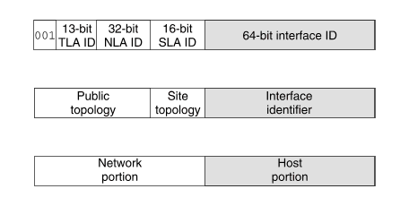
Aggregatable global unicast IPv6 address format (RFC 2374)
The address has the following components:
00120 through 3F.
FFFE to produce an EUI-64 address
with the format
ccccccFFFEeeeeee.
This step does not change the hardware address if it was already in EUI-64 form.
For example, the 48-bit MAC address 00A0244BEA8C becomes
00A024FFFE4BEA8C in EUI-64 format.
Setting bit 7 to 1 produces the value 20A024FFFE4BEA8C
which corresponds to
the interface ID 20A0:24FF:FE4B:EA8C
when written in IPv6 notation.
Interface IDs for nodes without hardware addresses (such as PPP link endpoints) must either be statically configured in software, assigned randomly, or assigned dynamically from a pool of available IDs.
The format prefix, TLA ID, and NLA ID define the location of an address within the public topology of the IPv6-based Internet. The SLA ID defines the topology of an organization's subnetworks, although, in practice, a service provider may only make part of this space available to an individual site depending on the requirements of the organization. The first 64 bits always define the network portion of an aggregatable global unicast IPv6 address, and the final 64 bits always define the host portion. The boundary between these does not move as is the case with IPv4 addresses.
IPv6 simplifies the IP header by moving some IPv4 fields to an extension header or by removing other fields entirely. It also defines a more flexible format for optional information (extension headers). The format of an IPv6 header is illustrated in ``IPv6 header format''.
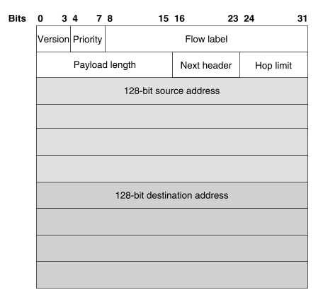
IPv6 header format
Specifically, IPv6 omits the following fields:
IPv6 options improve over IPv4 by being placed in separate extension headers that are located between the IPv6 header and the transport-layer header in a packet. Most extension headers are not examined or processed by any router along a packet's delivery path until it arrives at its final destination. This mechanism improves router performance for packets containing options. In IPv4, the presence of any options requires the router to examine all options.
Another improvement is that IPv6 extension headers, unlike IPv4 options, can be of arbitrary length and the total amount of options that a packet carries is not limited to 40 bytes. This feature, and the manner in which it is processed, permit IPv6 options to be used for functions that were not practical in IPv4, such as the IPv6 Authentication and Security Encapsulation options.
By using extension headers, instead of a protocol specifier and options fields, newly defined extensions can be integrated more easily into IPv6.
Following are some example IPv6 extension headers defined in current specifications:
While quality of service can be controlled by using a control protocol such as RSVP, IPv6 uses the priority field in the IP header to provide an explicit priority definition. A node can set this value to indicate the relative priority of a particular packet or set of packets. The node, routers, or the destination host can use the value to decide what to do with the packet, such as letting it pass or dropping it.
IPv6 specifies priorities for congestion-controlled and non-congestion-controlled traffic. No relative ordering is implied between the two types.
Congestion-controlled traffic is defined as traffic that responds to congestion through a ``back-off'' or other limiting algorithm. Priorities for congestion-controlled traffic are:
Non-congestion-controlled traffic is defined as traffic that responds to congestion by dropping (or simply not resending) packets. Examples are video, audio, or other real-time traffic. The ordering or the priority values is similar to that for congestion-controlled traffic with the lowest and highest values being used for traffic that the source is most and least willing to have discarded respectively.
Priority control is only applied to traffic from a particular source address. For example, control traffic from one address does not have a higher priority than attended bulk transfer from a different address.
Besides basic prioritization of traffic, IPv6 defines a mechanism for specifying a packet flow. A flow is defined as a sequence of packets sent from a particular source to a particular (unicast or multicast) destination for which the source desires special handling by the intervening routers.
Flow identification may be used for priority control, and it can also be used for any number of other controls.
The randomly chosen flow label does not identify any characteristic of the traffic other than the flow to which it belongs. This means that a router cannot determine the purpose of a packet (for example, one used by FTP) by reading the flow label. The router will, however, be able to determine that the packet forms part of the same sequence of packets as the previous packet that had the same label.
An IPv4 packet size is limited to 64KB. Using the jumbo payload extension header, an IPv6 packet can be up to 2^32 octets (4GB) long.
The key to successful transition from IPv4 to IPv6 is to preserve compatibility with the existing installed base of IPv4 hosts and routers. Maintaining compatibility with IPv4 while deploying IPv6 will make the task of transitioning the Internet to IPv6 much easier.
In most cases, the IPv6 routing infrastructure will evolve over time. While the IPv6 infrastructure is being deployed, the existing IPv4 routing infrastructure can remain functional, and it can be used to carry IPv6 traffic. Tunneling allows the existing IPv4 routing infrastructure to carry IPv6 traffic.
Dual-stack hosts and routers (that support both IPv4 and IPv6) can tunnel IPv6 datagrams over regions of IPv4 routing topology by encapsulating the IPv6 datagrams within IPv4 packets. Tunneling can be used in a variety of ways:
In Release 7.2 the Simple Internet Transition (SIT) mechanism (see RFC 1933) is used to implement such host-to-host connections. The sit interface implements the SIT mechanism.
Tunneling techniques are usually classified according to the mechanism by which the encapsulating node determines the address of the node at the end of the tunnel. In the router-to-router or host-to-router methods, the IPv6 packet is being tunneled to a router. In the host-to-host or router-to-host methods, the IPv6 packet is tunneled all the way to its final destination.
The entry point of the tunnel (the encapsulating node) adds the IPv4 header and transmits the encapsulated packet. The exit point of the tunnel (the decapsulating node) receives the encapsulated packet, removes the IPv4 header, updates the IPv6 header, and processes the IPv6 packet.
To process IPv6 packets forwarded into the tunnel, the encapsulating node maintains soft state information for each tunnel, such as its maximum transmission unit (MTU),
A host with two or more active interfaces is termed a ``multihomed host''. Each interface of a multihomed host has an associated link-local address. Link-local addresses are sufficient to allow communication among nodes attached to the same subnet.
In the IPv6 implementation in UnixWare 7 Release 7.2, link-local address resolution for multihomed hosts may be configured in one of four ways:
The Internet Control Message Protocol (ICMP) handles error and control messages for IP. This protocol allows gateways and hosts to send problem reports to the machine sending a packet. ICMP uses the basic support of IP as if it were a higher-level protocol. However, ICMP is actually an integral part of IP and is implemented by every IP module. There are two versions of ICMP, ICMPv4 and ICMPv6, which correspond to versions 4 and 6 of IP.
ICMP carries out error reporting, router discovery, and diagnostic testing on behalf of IP. ICMPv6 additionally assumes the functions that IGMP and ARP perform for IPv4: it distributes information about the membership of multicast groups and it resolves IPv6 addresses to hardware MAC addresses.
ICMP provides feedback about problems in the communications environment, but it does not make IP reliable. ICMP does not guarantee that an IP packet is delivered reliably, or that an ICMP message will be returned to the source host if an IP packet is not delivered or is delivered incorrectly.
ICMP sends and receives the following message types:
The Internet Group Management Protocol (IGMP) is used to provide information about membership of multicast groups on a network. Multicasting allows the efficient distribution of information to many hosts without requiring that inefficient alternatives such as multiple host-to-host transmissions, and broadcasting be used. Multicasting also allows clients to locate servers without broadcasting by requesting membership of the multicast group that the server maintains.
Hosts that wish to join a multicast group instruct their network adapter cards to listen for network frames specifying a special MAC address that corresponds to the multicast class D IPv4 address of the group. (In practice, the mapping is not unique, so the IPv4 module also has to perform some filtering of received frames.)
The data link layer protocols, ARP and RARP, resolve IPv4 addresses to MAC addresses and MAC addresses to IPv4 addresses for hosts on directly connected local networks.
The Address Resolution Protocol (ARP) is a data link layer protocol. ARP dynamically translates IPv4 addresses into the corresponding unique MAC addresses on local area networks (LANs).
Within a LAN, nodes address each other using MAC addresses written into the frame headers of network packets. Nodes on the same segment of a LAN use ARP to determine the MAC addresses of other nodes. A node broadcasts an ARP request for the MAC address of another node. The request contains the IP address for which the corresponding MAC address is needed together with the IP address and MAC address of the local host. If the target host receives the request, it places an entry for the sending host in its ARP cache (which is used to map quickly between IP addresses and MAC addresses), and it then replies directly with an ARP response containing its own IP address and MAC address. When the local host receives the response, it updates its own ARP cache.
Once an ARP cache entry exists, the local host can send network packets directly to the other host. If the ARP cache entry is deleted or expires, the host must resort to using ARP again to contact the other system.
Unlike most protocols, the format of ARP packets is not fixed. It depends on the variety of network technology (such as Ethernet or Token-Ring) that is being used.
Entries in the ARP cache are deleted after 20 minutes,
and incomplete entries are deleted after 3 minutes.
To make a permanent entry in the ARP mapping tables,
specify the pub parameter to the
arp(1Mtcp)
command, for example:
arp -s 802.3 host2 0:dd:0:a:8s:0 pub
The Reverse Address Resolution Protocol (RARP) was used by early network client machines to discover their IPv4 address at boot time. It has been superseded by higher level protocols such as BOOTP and DHCP.
The physical layer is the hardware level of the protocol model that is concerned with electronic signals. Physical layer protocols send and receive data in the form of packets.
A packet contains a source address, the transmission itself, and a destination address.
TCP/IP supports a number of different hardware at the physical layer including Ethernet, Token-Ring, and Fiber Distributed Data Interface (FDDI) on local area networks (LANs). It also supports the PPP and SLIP point-to-point protocols used with wide area networks (WANs) established over the public telephone system.
If you ever expect to communicate on the Internet, as opposed to just connecting a few hosts together locally with no outside connections, you or your Internet Service Provider (ISP) must apply to a Network Information Center (NIC) for a domain name and an IP network address.
If you want to connect your network to the Internet, you must obtain an IP address for it that defines a range of host addresses that you can use. If you do not want to change existing network addresses, you will probably need to connect via an address translation gateway. Other information that you need to register includes your domain name and address-to-host lookup information (your IN-ADDR.ARPA domain). If you are setting up a gateway as an autonomous system (AS) that will use the EGP or BGP routing protocols to pass reachability information to other systems, you will also need to register this.
In the first instance, contact a local ISP if you want to connect a corporate network to the Internet. The service provider should be able to register the details of your organization's networks for you. You would normally only register directly with a Network Information Center if you are setting up an autonomous system or intend to provide Internet services yourself.
The NICs prefer that administrators obtain an IP address range for their networks from an Internet Registry (IR). This will usually be done via a service provider. If you do not know of a suitable service provider, most NICs will forward requests for connection to a mailing list of suitable ISPs. The service providers will then contact you if they are interested.
If you want to register a domain name, contact your service provider rather than an NIC or a domain administrator. Only the InterNIC handles the registration of three-letter domain names such as COM, ORG, and NET. The other NICs do not handle domain name registration. If you want to register a domain within a two-letter top-level domain (such as the geographical domain uk), you must contact the administrator for that domain. You can obtain more information about who to contact for domain registration from the NICs.
Information about registering domain names with InterNIC Registration Services is given at the URL http://rs.internic.net. InterNIC Registration Services may be reached using the contact information given at the URL http://www.networksolutions.com.
Information about registering IP addresses and Autonomous System Numbers (ASNs) with the American Registry for Internet Numbers (ARIN) is given at the URL http://www.arin.net/regserv.html.
Networks that will be connected/located within the geographic region maintained by the Asia Pacific NIC can obtain more information at the URL http://www.apnic.net.
European network applications can obtain more information at the URL http://www.ripe.net.
The central coordinating organization for the assignment of unique parameter values for the Internet protocols is the Internet Assigned Numbers Authority (IANA). IANA is a not-for-profit organization which handles the assignment of parameters such as protocol and port numbers. More information is available at the URL: http://www.iana.org/.
SCO TCP/IP and other manual pages frequently cite appropriate RFCs (Requests for Comments). RFCs can be obtained via the World Wide Web at the URL http://www.rfc-editor.org.
``For more about the Internet protocols'' lists RFCs that relate to the Internet protocols.
To obtain more information about the Internet protocols, see the following RFCs.
| RFC | Title |
|---|---|
| 768 | User Datagram Protocol |
| 791 | Internet Protocol |
| 792 | Internet Control Message Protocol |
| 793 | Transmission Control Protocol |
| 1112 | Host Extensions for IP Multicasting |
| 1122 | Requirements for Internet hosts - communication layers |
| 1700 | Assigned Numbers |
| 1883 | Internet Protocol, Version 6 (IPv6) Specification |
| 1885 | Internet Control Message Protocol (ICMPv6) for the Internet Protocol Version 6 (IPv6) Specification |
| 2236 | Internet Group Management Protocol, Version 2 |
| 2373 | IP Version 6 Addressing Architecture |
| 2374 | An IPv6 Aggregatable Global Unicast Address Format |
| 2375 | IPv6 Multicast Address Assignments |
| 2500 | Internet Official Protocol Standards |